ARTES
ARTES is a browser-based computational fluid dynamics workspace. This presentation shows engineering model preparation and the visualization of simulation results.
[00]
Leverage Our Expertise for Your Strategic Growth
Move from design through simulation and analysis to optimized results in one connected CFD workflow.
NSMB Solver
Connect your ARTES workflow with CFSE's NSMB flow solver, from case setup to simulation results.
Seamless Browser-Based Integration
Prepare, run, and review CFD work in one browser-based workspace, with a smooth handoff between steps.
- Design
- Mesh
- Simulate
- Analyze
- Optimize
%20--%3e%3csvg%20width='18.163717mm'%20height='23.957724mm'%20viewBox='0%200%2018.163717%2023.957724'%20version='1.1'%20id='svg1'%20xmlns='http://www.w3.org/2000/svg'%20xmlns:svg='http://www.w3.org/2000/svg'%3e%3cdefs%20id='defs1'%20/%3e%3cg%20id='layer1'%20transform='translate(-185.33775,-144.47686)'%3e%3cpath%20d='m%20189.45051,144.47689%20c%20-0.21983,-0.002%20-0.34877,0.24664%20-0.22066,0.4253%20l%204.84157,6.75359%20c%200.91125,1.25653%201.31903,2.37176%201.5012,3.2458%20l%206.58399,1.2485%20c%200.34273,0.057%200.34273,0.54967%200,0.60668%20l%20-6.58399,1.2485%20c%20-0.18217,0.87418%20-0.58996,1.9898%20-1.5012,3.24632%20l%20-4.84157,6.75359%20c%20-0.18646,0.25708%200.14887,0.56806%200.39119,0.36277%20l%2013.64258,-11.40551%20c%200.31714,-0.26524%200.31714,-0.75278%200,-1.01802%20l%20-13.64258,-11.40499%20c%20-0.0479,-0.04%20-0.10815,-0.0621%20-0.17053,-0.0625%20z'%20style='fill:%23ffffff;stroke-width:1.63239;stroke-linecap:square'%20id='path41'%20/%3e%3cpath%20d='m%20195.57262,158.00526%20c%200.1413,-0.67806%200.14676,-1.2108%200.14676,-1.55184%200,-0.34104%20-0.005,-0.8739%20-0.14676,-1.55184%20l%20-9.92963,-1.64848%20a%200.26104936,0.26104936%200%200%200%20-0.15503,0.49299%20l%202.73627,1.3038%20c%200.62441,0.29707%201.03078,0.77701%201.01234,1.40353%200.0184,0.62651%20-0.38793,1.10646%20-1.01234,1.40353%20l%20-2.73679,1.3038%20a%200.26111711,0.26111711%200%200%200%200.15555,0.49351%20z'%20style='fill:%23ffffff;stroke-linecap:square;stroke-linejoin:round'%20id='path39'%20/%3e%3c/g%3e%3c/svg%3e)
Made for Aerospace Applications
Build and study demanding aerospace cases, from vehicle geometry and meshes to re-entry flow fields.
Integrated Post-Processing
Explore physical fields and simulation results directly in ARTES, without leaving your workflow.
[01]
Define your geometry
Shape your model and organize its parts into a simulation-ready setup.
[02]
Mesh
Inspect the CARINA computational grid and its three-dimensional block structure.
ARV-2 to CARINA capsule family viewport
[03]
Simulate
Set up the case and run a high-fidelity flow simulation.
[01]
Easy Setup
Define free stream conditions from a planetary atmosphere, or enter the values yourself.
| Free stream density. | ||
| Free stream pressure. | ||
| Free stream temperature. | ||
| Gas constant (287.0 for air, set to 1 if variables are non-dimensionalized). | ||
| Reynolds number per meter. Depending on the viscosity model, may be ignored since it is computed from free stream conditions. |
[02]
Run simulations on a sustainable cloud
Swiss-hosted infrastructure supports digital sovereignty and keeps simulation data under your control.

[04]
Post-Processing
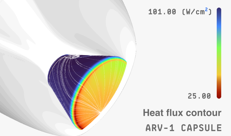
Access physical fields during re-entry. Examine the bow shock, stagnation line, and high-temperature regions around the vehicle.
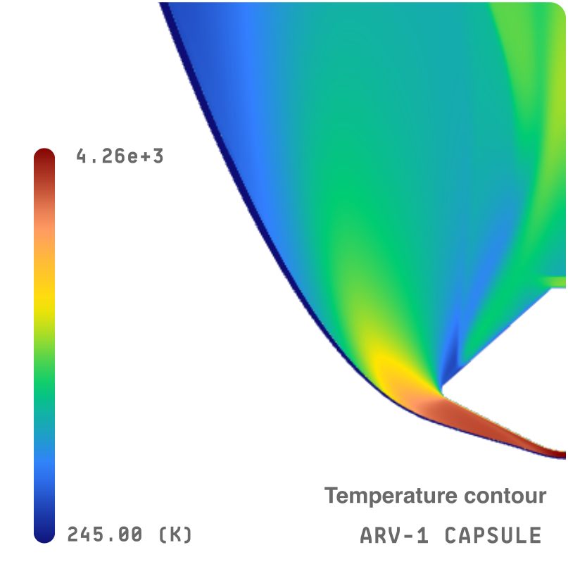
Bow-shock
Trace the shock front.
Inspect the Mach field ahead of the vehicle.
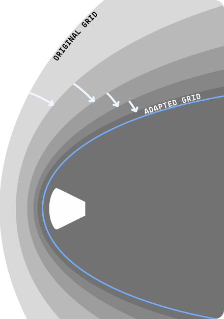
Stagnation-line
Follow the centerline flow.
Study heat flux near the vehicle nose as the incoming flow slows.